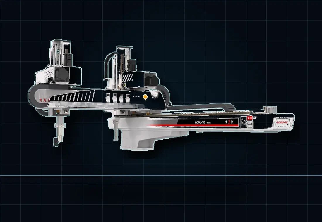
The right injection moulding robot is the smallest suitable system that can safely clear the mould within the available cycle window, carry the complete end-of-arm tool and product load, reach every required position and present the part correctly to its next operation. Moulding-machine tonnage alone is not enough to choose it.
Which robot type suits the application?
Robot names overlap. A “take-out robot”, “linear robot”, “Cartesian robot”, “sprue picker” or “machine-tending robot” may describe different levels of capability. Define the motion and process before comparing model numbers.
| Robot type | Strong fit | Watch points |
|---|---|---|
| Sprue picker or swing-arm manipulator | Simple runner removal, short transfer and basic drop-off where orientation is not critical. | Limited payload, stroke, sensing and downstream flexibility. It may not protect finished parts. |
| 3-axis Cartesian or linear robot | Fast top-entry take-out, runner handling and repeatable placement on a conveyor or chute. | Check wrist/orientation needs, usable strokes, mould-entry time and EOAT access. |
| 5-axis Cartesian servo robot | Part and sprue handling, angled release, orientation, stacking and more controlled downstream placement. | Payload must include wrist and tooling; added motion needs a realistic cycle study. |
| Side-entry robot | Very short cycles, packaging applications and processes such as in-mould labelling where lateral access is advantageous. | Machine-side space, guarding, product discharge and mould access need early layout work. |
| Six-axis industrial robot | Complex orientation, insert loading, trimming, inspection, assembly, multi-station handling and flexible changeover. | Mould-entry path, floor space, guarding and speed can make a simple take-out task unnecessarily complex. |
| Collaborative robot | Lower-speed downstream work where flexible deployment and appropriate collaborative operation can be proven. | A cobot does not make the complete application safe. Hot parts, EOAT and moulding-machine hazards still require assessment. |
How should payload be calculated?
Payload is the complete moving load, not only the moulded component. Include every part from a multi-cavity shot, the sprue or runner, gripper frame, vacuum cups or fingers, wrist equipment, valves, sensors, quick-change components, hoses carried by the arm and any insert payload.
Required payload = EOAT + all products + runner/sprue + carried services + engineering allowanceThe robot must also support the load at the required speed, acceleration and extension. A nominal catalogue payload is not a complete dynamic check.
Which strokes and clearances matter?
Use the real mould and machine geometry. Record the mould-open stroke, daylight, platen and tie-bar arrangement, machine height, tool depth, ejector stroke, core movements, product release direction and the point at which the robot is genuinely clear for mould closure.
- Vertical stroke: reach the deepest pickup point and clear the machine or guarding.
- Traverse stroke: reach the discharge, conveyor, fixture or downstream station.
- Kick or approach stroke: enter the mould without contacting tie bars, cores or tooling.
- Rotation and wrist axes: release the part and present it in the required orientation.
How does cycle time change the choice?
The robot's total automatic cycle is less important than the time it occupies the mould area. Break the sequence into mould-open confirmation, entry, pickup, grip confirmation, extraction, mould-clear confirmation and downstream work. Secondary operations can often continue while the next moulding cycle runs, but only if the layout and control sequence allow it.
Ask for a sequence study based on the actual part, strokes and tooling mass. Catalogue axis speeds do not prove a finished cell cycle.
Why must EOAT be designed with the robot?
End-of-arm tooling (EOAT) determines how the system grips, supports, senses and releases the moulding. Hot, soft or cosmetic parts may need distributed vacuum support; inserts can need compliance and positive presence checks; multi-cavity parts may need individual sensing or cavity identity through the whole downstream process.
A lighter tool can permit a smaller robot and faster motion, but stiffness, heat, hose routing, maintenance access and safe failure behaviour cannot be sacrificed simply to reduce mass.
What machine-interface information is required?
Confirm the moulding-machine make, model, controller, age and available robot interface. EUROMAP 67 describes a hard-wired electrical interface between an injection moulding machine and a handling device or robot; newer equipment may support broader data exchange. The final handshake still has to match the machine, robot, ejector/core sequence and complete safety concept.
Typical sequence information includes mould open, ejector positions, core positions, reject status, robot clear and permission to close. Interface availability should be checked before assuming an older machine is “robot ready”.
What should be in a robot project brief?
- Machine: make, model, clamp tonnage, controller, platen and mounting information.
- Mould: dimensions, opening, ejectors, cores, cavities, release direction and access restrictions.
- Product: dimensions, mass, temperature, surfaces, gripping areas and acceptable deformation.
- Runner or sprue: geometry, weight and required destination.
- Cycle: current and target cycle, mould-open window and any cooling constraints.
- Output: drop, conveyor, orientation, inspection, assembly, packing or cavity separation.
- Site: available floor/overhead space, guarding, access, utilities and preferred operator flow.
Injection moulding robot selection FAQs
01What type of robot is most common for injection moulding?
A top-entry Cartesian or linear robot is a common choice for repeatable part and runner removal because its straight axes suit the fixed mould-to-drop or mould-to-conveyor path. The correct architecture still depends on cycle time, strokes, payload, orientation and downstream work.
02Is moulding-machine tonnage enough to size a robot?
No. Tonnage is a starting reference, but usable strokes, platen and mounting details, mould opening, part and sprue envelope, EOAT mass, payload, cycle window and discharge position all affect the final selection.
03When is a six-axis robot better than a Cartesian robot?
A six-axis robot is useful when the part needs complex orientation, angled access or several downstream operations. A Cartesian robot can be the better choice when fast vertical mould entry, a compact footprint and repeatable linear transfer are the priorities.
04Can a robot be fitted to an existing injection moulding machine?
Often, yes. A retrofit assessment must confirm mechanical mounting, strokes, interface signals, guarding, safe access, controller compatibility and enough space for the required product flow.