Mechanical fit
Review platen or beam mounting, machine structure, overhead clearance, mould opening, vertical and traverse strokes, tie bars, guarding and maintenance access.
Add repeatable part take-out, sprue handling, insert loading or downstream transfer to an existing injection moulding machine—with the mounting, interface, EOAT, guarding and product flow assessed together.
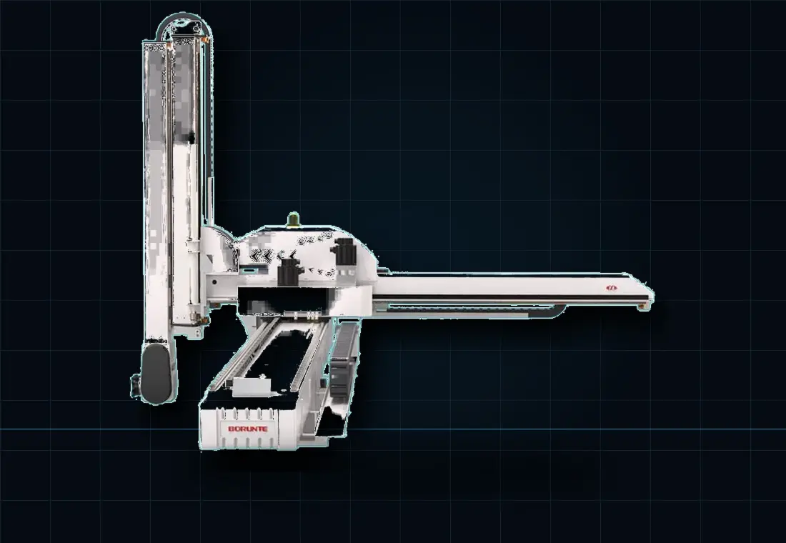
Often, yes. A successful retrofit depends on more than matching robot size to clamp tonnage. The machine must offer suitable mechanical mounting and mould access, usable interface signals, a controllable ejector/core sequence, a workable safety concept and enough space to move the product to its next destination.
A site or video assessment can identify the questions quickly. Machine and mould drawings allow the final strokes and access to be proven.
Review platen or beam mounting, machine structure, overhead clearance, mould opening, vertical and traverse strokes, tie bars, guarding and maintenance access.
Confirm the available robot connector or signals, controller condition, ejectors, cores, mould-clear sequence, reject handling and emergency-stop integration.
Define whether the robot drops, separates, orients, inspects, cools, trims, assembles or packs the product. The destination changes the whole system.
Send a machine data plate image, overall cell photographs and a short cycle video, then support them with the engineering details needed to verify the concept.
Send machine detailsScope is matched to the application and can extend from simple take-out to a coordinated mould-to-pack cell.
Select the architecture, strokes, payload, wrist and mounting arrangement from the proven machine and mould envelope.
Design the gripper around part temperature, release, surfaces, cavities, runner handling, utilities and positive grip confirmation.
Coordinate machine, robot and downstream signals, including mould-clear permission, rejects, failed pickup and controlled restart.
Add separation, conveyors, nests, cooling, inspection, counting or packing interfaces where they create a stable downstream process.
Define guarding, interlocks, operator loading, maintenance access and responsibilities for the integrated cell.
Plan downtime, site preparation, commissioning, acceptance, training, spares and production support before the machine is stopped.
Not every machine is suitable without modification. The assessment must confirm robot mounting, mould access, usable strokes, controller and interface signals, ejector and core sequence, guarding, safe access, structural condition and enough space for the product destination.
Provide the machine make, model, tonnage, controller and year; platen and mounting details; mould dimensions and opening; part and runner data; cycle time; interface information; layout photographs; and the required downstream hand-off.
It can where payload, strokes, access and cycle time support the combined sequence. The end-of-arm tool, insert presentation, presence checks and recovery logic must be designed with the existing mould and machine interface.
A complete project can include the robot, EOAT, interface, controls, conveyors, guarding, installation, commissioning and training. The agreed quotation should state the conformity route and responsibilities for the integrated cell.
Send the nameplate, mould details, part and runner information, layout photographs and a short cycle video.