Reliable pickup
Grip points, cups, fingers and support surfaces are placed around the actual release behaviour, hot-part stiffness and allowable contact areas.
End-of-arm tooling designed around the mould, product, runner, temperature, release direction, sensing requirement and next production operation.
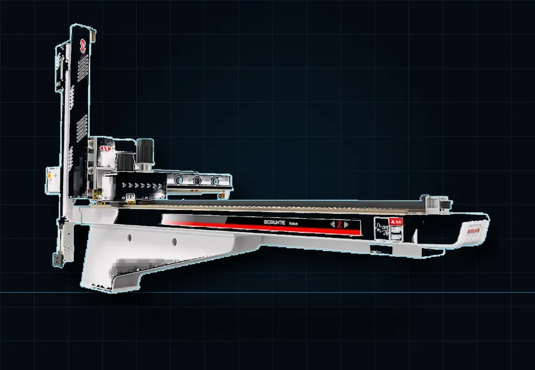
End-of-arm tooling is the application-specific equipment attached to a robot or manipulator. It makes contact with the moulded parts, sprues, runners or inserts and determines whether the automatic cycle can grip reliably, confirm pickup, clear the mould, protect the product and release it in the correct position.
EOAT mass, stiffness, geometry and services affect robot payload, acceleration, mould access, cycle time and maintenance. It should be developed with the robot and cell layout.
Grip points, cups, fingers and support surfaces are placed around the actual release behaviour, hot-part stiffness and allowable contact areas.
Vacuum switches, part-present sensors, jaw confirmation or vision can prevent an incomplete pickup becoming a mould or quality problem.
The tool maintains cavity identity and orientation where parts move into cooling, inspection, assembly, trays, conveyors or packaging.
Early samples and 3D data reduce uncertainty, but the design also needs the dynamic production conditions that drawings may not show.
Send tooling detailsMany moulding tools use several gripping and verification methods on one lightweight frame.
Suitable cup material, shape and distribution can support large or delicate surfaces. Vacuum generation, leakage and confirmation thresholds must suit the real part.
Parallel, angular or custom fingers can grip ribs, bosses, runners and edges where positive retention is required.
Some soft, textile or difficult surfaces need application-specific gripping methods assessed against product damage and maintenance.
Independent gripping and sensing can keep finished components separate from runners and route both streams correctly.
Compliant location, positive retention and pickup/placement checks help protect the mould before permission to close is released.
Mechanical, pneumatic and electrical quick-change arrangements can shorten product changeovers when alignment, identification and safe service isolation are designed in.
End-of-arm tooling is the application-specific equipment attached to the robot wrist or arm. It grips, supports, senses, separates and releases the moulded parts, runners or inserts required by the automatic cycle.
The choice depends on part geometry, surface, temperature, stiffness, draft, release force and acceptable grip areas. Many tools combine vacuum, mechanical fingers, runner grippers and sensors rather than relying on one method.
Yes, when the robot payload, mould access and cycle allow it. Separate circuits and sensing can confirm the finished part and runner before the tool clears the mould and routes each stream to the correct destination.
Provide 3D product and mould data where available, part and runner samples, weights, cavity layout, release direction, temperature, surface requirements, cycle time, robot details, utilities and the required placement or downstream operation.
Include samples or 3D data, cavity layout, release sequence, cycle target, surface requirements and the intended placement destination.