Stable cycle time
Repeatable entry, grip confirmation and mould-clear signals help make extraction predictable from cycle to cycle.
Remove finished components at a repeatable point in the moulding cycle, protect critical surfaces and transfer each part into the next controlled operation. We engineer the robot, end-of-arm tooling, machine interface and downstream hand-off as one system.
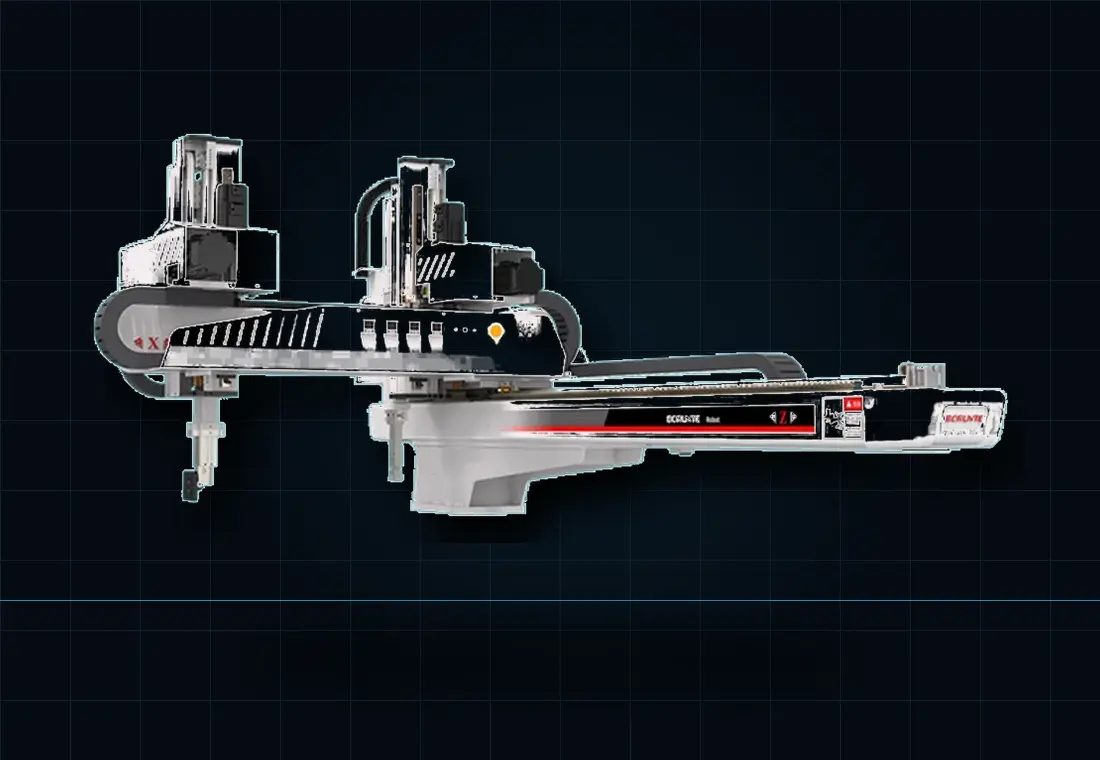
The robot is one element in a coordinated production system. The strongest result comes from defining the product, mould sequence and next operation together.
Repeatable entry, grip confirmation and mould-clear signals help make extraction predictable from cycle to cycle.
Tooling is matched to the part geometry, surface finish and temperature to reduce marking, distortion and uncontrolled drops.
Parts can leave the cell in the orientation needed for inspection, trimming, assembly, conveying or packing.
We define the equipment and interfaces required to turn a representative robot platform into a workable moulding-cell solution.
See how we integrate cellsWe document the mould-open position, ejector sequence, allowable entry window and safe clear signal before defining robot motion.
Part geometry, mould temperature, surface sensitivity and draft condition determine cup material, jaw design and sensing.
The extraction is only complete when the part has been placed, verified and released without creating a downstream bottleneck.
Often, yes. The assessment needs the machine make and model, platen and mounting details, available stroke space, controller interface, guarding arrangement and the complete mould sequence.
We use the complete moving payload, vertical and traverse strokes, part-release window, moulding-machine tonnage, required orientation and downstream destination. Machine tonnage alone is not enough.
Yes, where the strokes, payload and access envelope cover every tool. Quick-change end-of-arm tooling, recipes and keyed services can make product changeovers more controlled.
Send the machine details, part and sprue information, target cycle and a photo or video. We will define the next engineering step.
Removing every moulding successfully does not automatically preserve which cavity produced each part. Once components fall into a common container, a later defect can be difficult to relate to one cavity or shot. Decide whether that association is needed before choosing the take-out tool and downstream presentation.
Provide the cavity layout, tool orientation and expected handling sequence. Where traceability is required, review whether the gripper and output fixture can retain a known position for each moulding until the relevant inspection or identification step. Include an incomplete shot, a missing grip and an intentionally rejected part in the sequence discussion, because each can break a simple assumption that the next output position always represents the next cavity.
The specification should state which information is retained, where it becomes attached to a part or carrier, and what happens when that association is uncertain. Not every moulding application needs individual marking; controlled trays or separate output routes may suit the agreed requirement. Send the mould cavity drawing and explain how quality issues are currently traced so the take-out and downstream inspection can be designed around the same objective.
Only if the handling and data arrangement maintains the required association; bulk collection can lose it.
Not always. A controlled carrier, known position or separate route may meet the defined process requirement, subject to assessment.
Plan moulded-part separation Connect take-out to quality inspection