Mould-open, ejector, core and cycle-permit signals.
Injection-moulding automation for UK manufacturers
Take the part.
Take the part.
Control what happens next.
Robots and manipulators for moulded-part take-out, sprue removal, insert loading, separation, orientation and direct transfer into downstream production or packaging.
01Matched to your moulding machine
02Tooling, controls & guarding
03Mould-to-pack integration
The application comes first
Robot selection follows the part, mould sequence, available stroke, cycle window and destination—not the other way round.
How we engineer the cell
Injection moulding robot solutions
One moulding cycle.
One moulding cycle.
Every handling step controlled.
Choose the production task closest to your requirement. Each system is then specified around the actual machine, tool, component, output and site constraints.
01
Cycle-consistent extraction
02
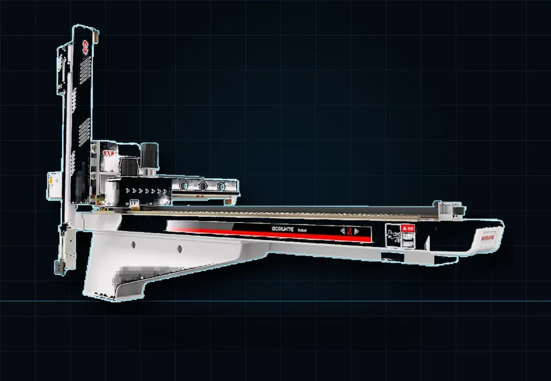
Moulded-part take-out robots
Remove finished components at a repeatable point in the moulding cycle, protect critical surfaces and transfer each part into the next controlled operation. We engineer the robot, end-of-arm tooling, machine interface and downstream hand-off as one system.
Explore solution
Controlled runner handling
03
Sprue removal and separation
Separate sprues and runners from saleable components without relying on uncontrolled drops or repetitive manual handling. The cell can remove both streams, verify separation and route material to the correct destination.
Explore solution
Repeatable in-mould placement
04
Insert-loading robot systems
Orient and place inserts into the mould before each injection cycle, with positive presence checks and controlled recovery. We can integrate feeding, presentation, end-of-arm tooling, machine handshakes and post-mould handling.
Explore solution
Ordered output from every shot
05
Component separation and sorting
Keep multi-cavity components ordered from the moment they leave the mould. Controlled placement, cavity tracking and reject routing can prevent mixed output and give downstream operations a predictable product flow.
Explore solution
From mould to next operation
06
Downstream placement and orientation
Do more than remove the part. The take-out robot or a secondary six-axis robot can orient, space and place components so inspection, assembly, cooling and packing receive stable, repeatable input.
Explore solution
Complete mould-to-pack flow
Conveyors and packaging integration
Connect the moulding cell to the equipment that turns individual cycles into packed production. We define conveyor flow, buffering, checks, counting, packing interfaces and safe control across the complete line.
Explore solution
The complete automation cell
A robot is only useful when
A robot is only useful when
the whole process works.
We bring the motion, gripping, machine signals, product flow and safety concept into one coordinated project.
Entry, grip, extract, orient and clear.
Presence, vision, separation and buffering.
Conveyor, assembly, inspection or packaging.
Representative robot platforms
From compact take-out
From compact take-out
to large-part handling.
These reference platforms show the range of architectures available. Final payload, strokes, speed and tooling are confirmed against your complete application.
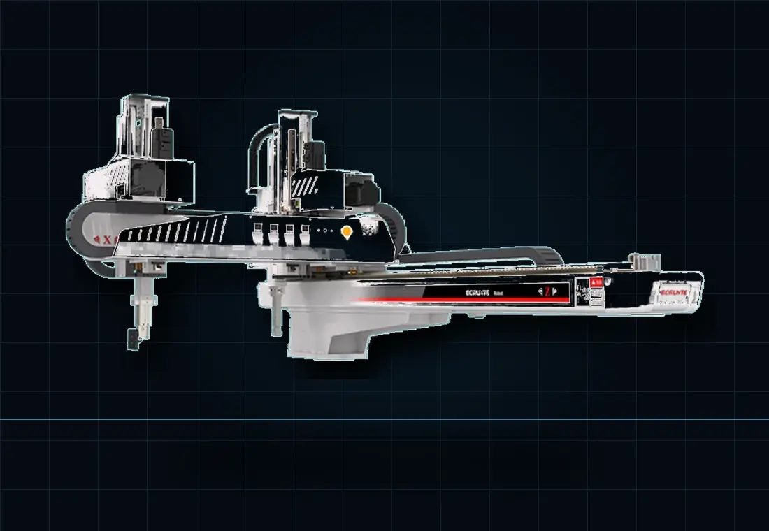
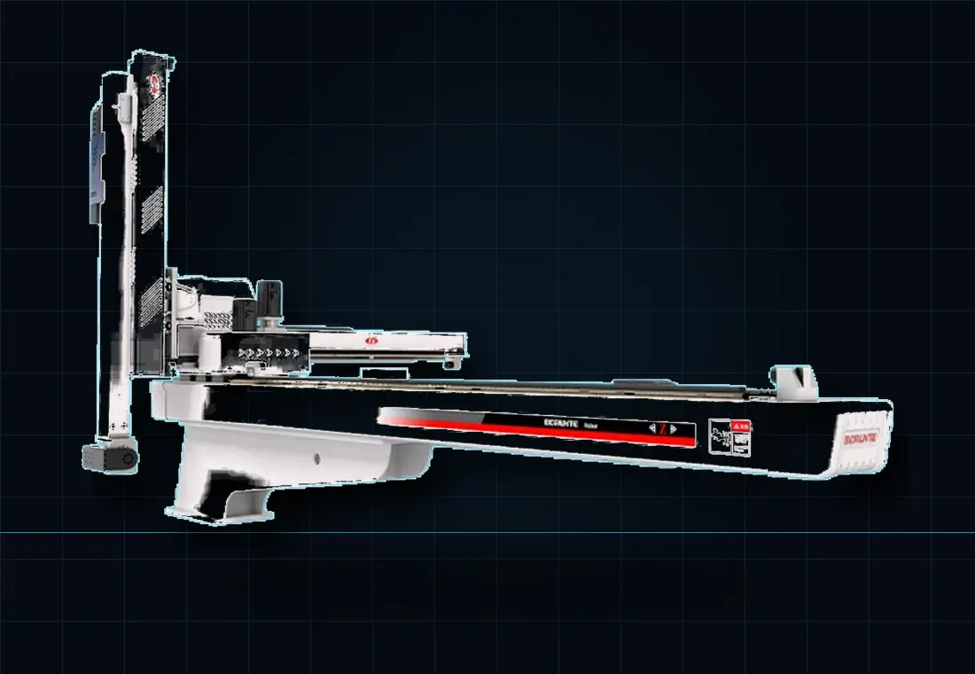
Compact moulding-cell manipulator
Cartesian Servo Take-Out Robot
Fast finished-part extraction, sprue handling and insert applications on compact to medium machines.
- 50T–230T machine range
- 5-axis AC servo
- Two-arm configuration
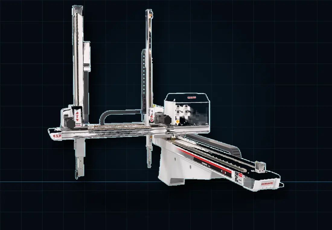
Dual-stream part and sprue handling
Fast-Action Servo Manipulator
Rapid take-out where saleable parts and runners need controlled separation and placement.
- 160T–320T machine range
- 5-axis servo
- Part + sprue handling
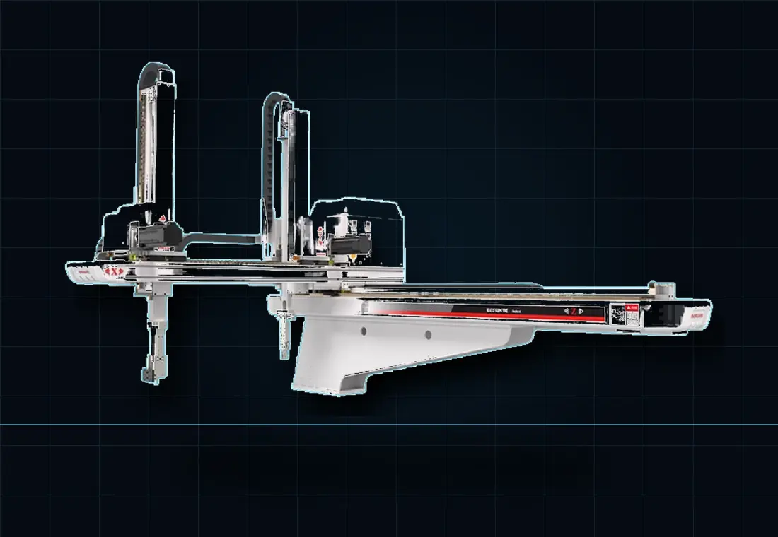
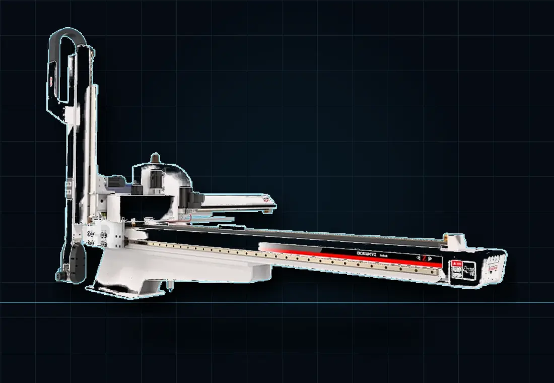
Five-axis Cartesian platform
Injection-Moulding Machine Robot
Moulded containers, packaging items and general components requiring repeatable extraction.
- 160T–320T machine range
- 5-axis Cartesian
- Telescopic vertical arm
Engineering the right cell
Start with the detail that changes the answer.
Small differences in mould construction, part release, presentation or downstream timing can change the robot, gripper and control strategy. Our first step is to collect the engineering facts.
Machine & mould
Make, model, tonnage, platen, mounting, mould-open stroke, ejectors, cores and interface signals.
Part & sprue
Dimensions, mass, cavities, temperature, surfaces, draft, release points and acceptable gripping areas.
Cycle & motion
Current cycle, robot entry window, vertical and traverse strokes, orientation and safe-clear point.
Next operation
Separation, cooling, vision, assembly, conveying, packing, counting, traceability or palletising.
Explore by robot, process or project stage
Practical routes into moulding automation.
Compare robot architectures, specialist applications and the engineering questions that determine a reliable UK injection-moulding cell.
Robot architecture
Cartesian servo robots
Top-entry, three-axis and five-axis take-out automation.
Compare options ↗ Runner handlingServo and pneumatic sprue pickers
Controlled sprue removal, separation and granulator transfer.
Explore sprue pickers ↗ PackagingIn-mould labelling automation
Label loading, static control, take-out, inspection and stacking.
Explore IML ↗ Insert loadingInsert moulding and overmoulding
Feeding, placement, presence checks and finished-part inspection.
Explore insert automation ↗ EOATRobot grippers and tooling
Vacuum, mechanical gripping, sensing and quick change.
Specify EOAT ↗ QualityMoulded-part vision inspection
Visible defect checks, cavity tracking and secure rejects.
Explore inspection ↗ Buyer guideRobot retrofit guide
Mounting, strokes, interface, guarding and commissioning.
Plan a retrofit ↗ ChecklistHow to specify a moulding robot
Collect the data that leads to a useful, comparable proposal.
Use the checklist ↗
More ways customers search
Compare architecture, finishing
Compare architecture, finishing
and commercial fit.
Use these focused guides to answer the decisions that normally arise before an injection-moulding automation project can be scoped.
Flexible robot architecture
Six-axis robots and cobots
Complex take-out, insert loading and post-mould operations.
Compare architectures ↗ Fast mould accessSide-entry robots
High-speed take-out, IML layouts and restricted headroom.
Compare entry options ↗ Component finishingRobotic degating and trimming
Gate cutting, flash removal, fixtures and quality checks.
Explore finishing ↗ Complete production flowPost-moulding automation
Cooling, inspection, assembly, testing and packing.
Map the process ↗ Investment planningRobot cost and ROI guide
Complete-cell cost drivers, benefits and payback inputs.
Build the business case ↗ Machine interfaceEUROMAP 67 guide
Robot handshakes, retrofit checks and commissioning.
Review the interface ↗
Project delivery
A clear route from
A clear route from
process review to production.
-
01 / Understand
Capture the real cycle
Review products, moulding machine, tool, rate, variants, layout and operator interaction.
-
02 / Engineer
Define the complete cell
Select the robot architecture, tooling, product flow, controls, interfaces and safety concept.
-
03 / Prove
Build, programme and test
Integrate equipment, prove motion and handling, run trials and close issues before installation.
-
04 / Deploy
Install and hand over
Commission on site, complete acceptance, train the team and agree support requirements.
Injection moulding automation FAQ
Useful answers.
Useful answers.
Better project briefs.
The final system is application-specific, but these questions cover the information needed to make an informed start.
01What information is needed to specify an injection-moulding robot?
Start with the moulding-machine make, model and tonnage; platen and mounting details; mould-open and ejector strokes; component and sprue dimensions and weights; cavity count; cycle time; required orientation; downstream destination; guarding; and any insert-loading requirement. Photos, layout drawings and a short process video are useful.
02Do you supply the robot arm only or the complete automation cell?
Oxford Industrial Automation focuses on the complete application. Scope can include the robot or manipulator, end-of-arm tooling, feeders, conveyors, vision, controls, machine interface, guarding, installation, commissioning and training.
03Can injection-moulding automation be retrofitted?
Many existing machines can be automated, but the available mounting, stroke envelope, controller signals, guarding and cycle sequence must be checked. A site or video assessment is normally the first step.
04Can one system remove parts and load inserts?
Yes, where the cycle window and payload support a combined operation. The end effector can collect finished parts and place inserts, with sensing used to confirm each pickup and release.
05How is the robot made safe with the moulding machine?
The solution requires a defined machine safety interface, guarding and interlocks, safe access arrangements and a risk assessment for the complete integrated cell. Final conformity responsibilities and documentation are agreed for each project.
Discuss your application
Start with the moulding process.
Send the machine details, part and sprue information, target cycle and a photo or video. We will define the next engineering step.
Can an existing injection moulding machine be retrofitted with a robot?
Record the moulding machine, mould access, part-removal sequence and available control interfaces. Include insert loading or downstream handling only where required. A feasibility assessment should establish the physical layout, cycle interactions, fault recovery and safeguarding changes, using the actual mould and parts before committing to the retrofit scope.